Op-Amp Helper
Op-Amps
Op-Amps (operational amplifiers) are integrated circuits that have been a bit annoying to work with in the past for me. Often they require rather odd power requirements — frequently positive and negative 9-volt power rails. I’ve bread-boarded op-amp circuits in the past and ended up with a couple of 9V batteries hanging off the end of the breadboard. It worked but wasn’t very pretty.
But, unrelated, I’m looking about online for circuits that generate white noise and stumble across an interesting circuit that involves running 18-volts in reverse across a transistor. The author admits that 18 volts is not a common voltage to have around but then mentions off-hand that a MAX232 integrated circuit provides something close to +9V and −9V from a simple 5V source.
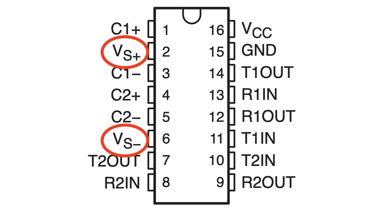
Oh, that’s interesting I think. I even happened to have been playing with the MAX232 chip recently and so had one already bread-boarded up. Sure enough, there are +9V and −9V (approximately) presented on two of the pins of the MAX232. (Wikipedia says +/− 7.5V, my data-sheet said +/−7V was typical, with no load I measured values around 9V — either way these are all adequate for most op-amp circuits.)
MAX232
The MAX232 chip was in fact created as a UART designed to handle incoming and outgoing serial traffic using the RS-232 protocol (hence the chip designator). The RS-232 specification apparently requires these rather unusual and large (and both positive and negative) voltages.
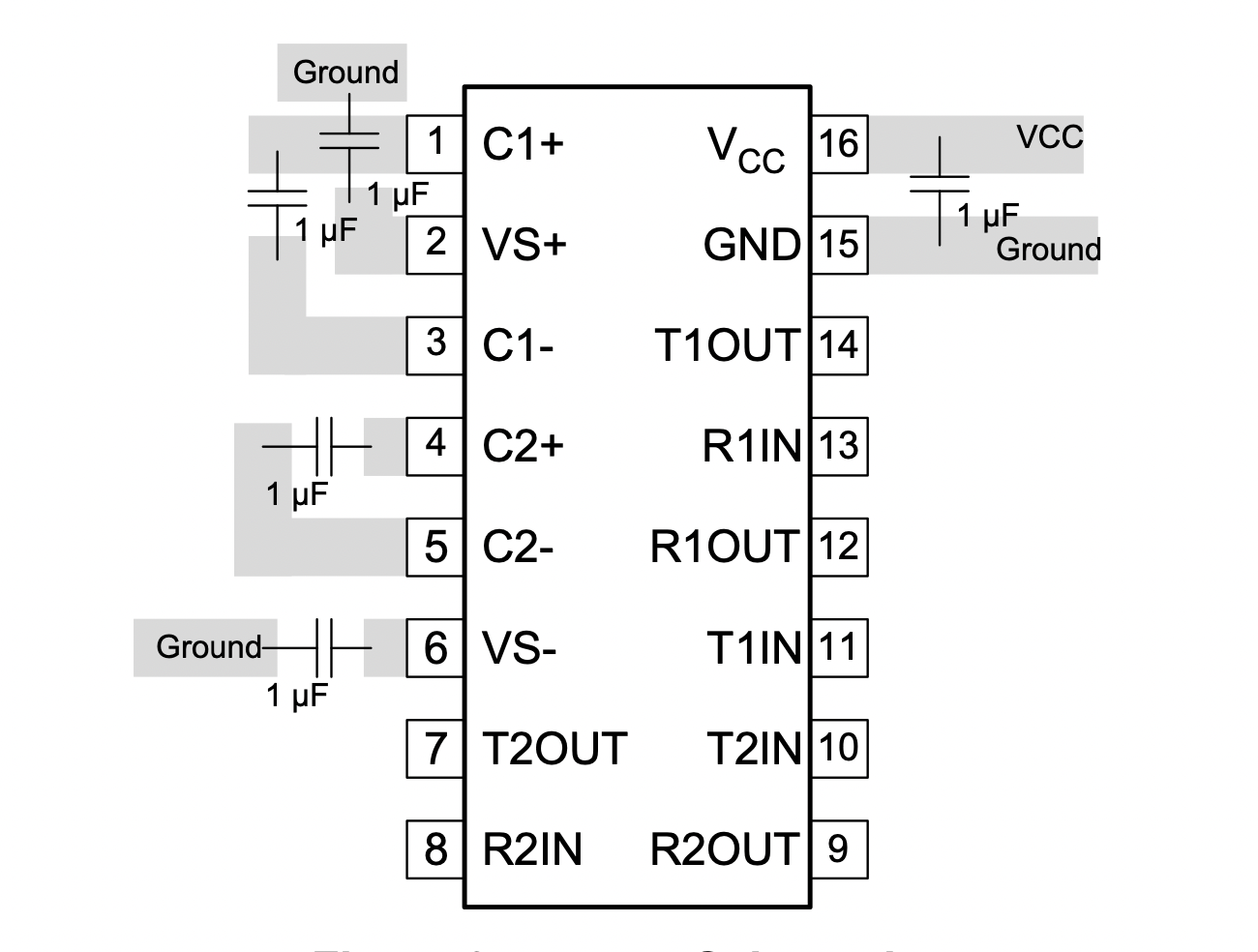
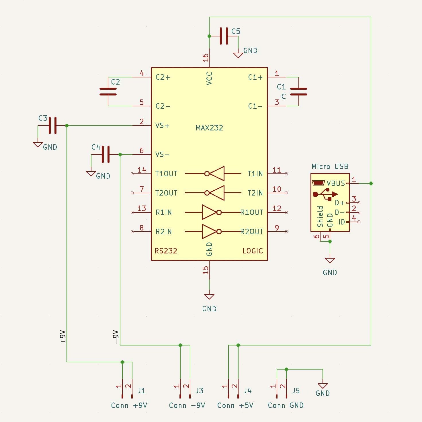
For the MAX232 to work this magic, creating +/− 9V from 5V, you do need to add a handful of external capacitors. The diagram below is taken from the data sheet and shows the five external capacitors (apparently 1 µF or 0.1 µF capacitors will work).
PCB
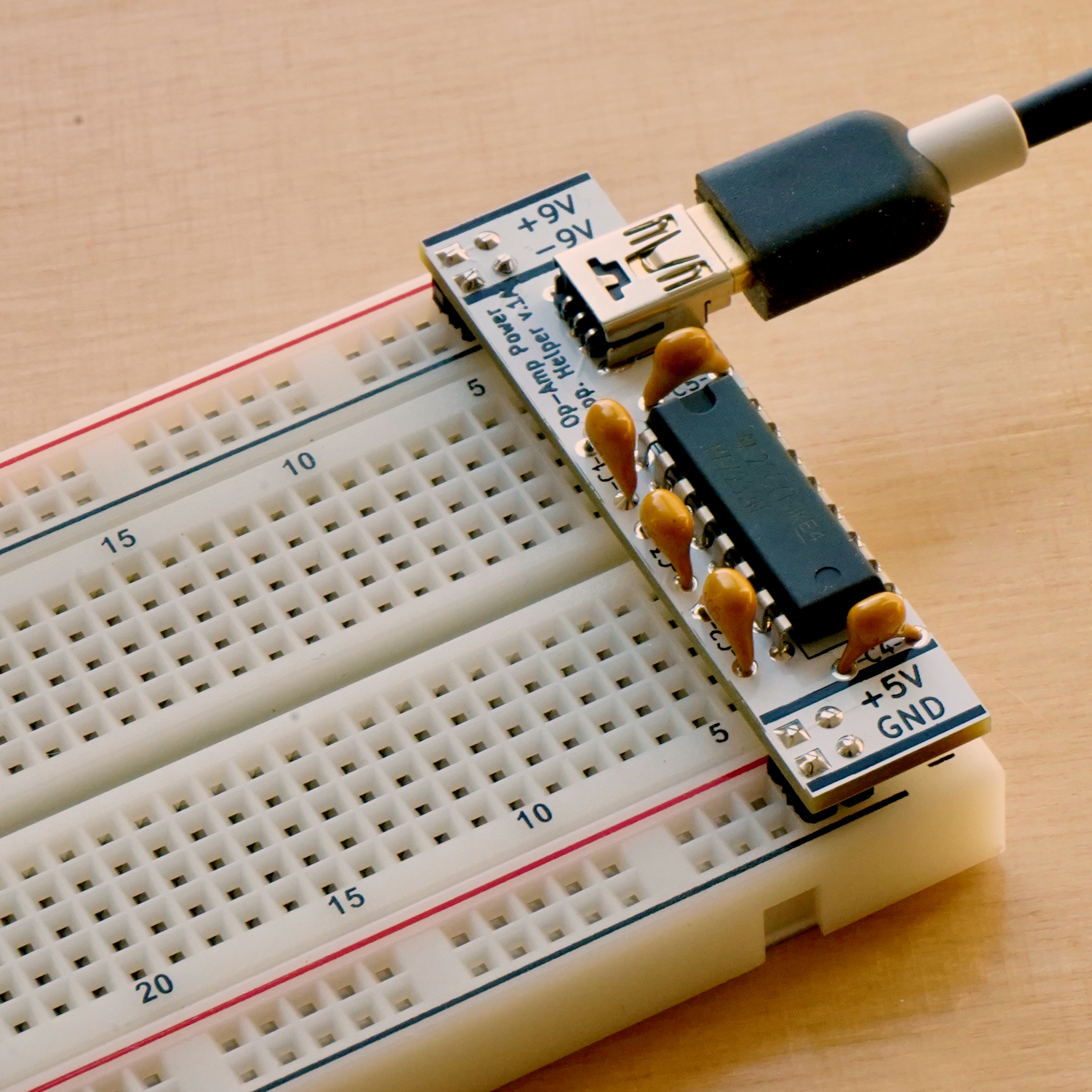
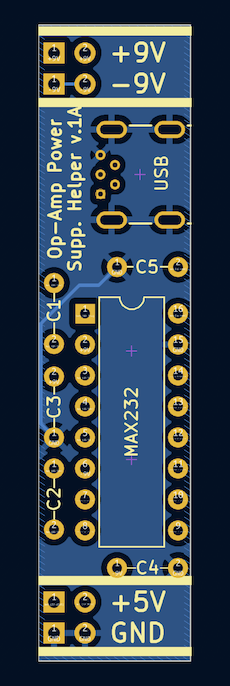
To make working with op-amps on the breadboard easier I created a simple printed circuit board (PCB) around this idea.
I like using USB to provide the 5 volts since USB power bricks are so ubiquitous these days. Unfortunately the only USB connector I could find that was through-hole (as opposed to surface-mount) was the Micro-B USB connector. (I’m not sure how common Micro-USB cables are these days though. They used to be common for mechanical keyboards and game controllers.)
The important part of the PCB layout was that I wanted it to span from the top pair of power rails to the bottom pair of power rails on a typical breadboard. In this way straight header pins could poke out of the bottom of the PCB and, when plugged into the power rails of a breadboard, provide the specified voltages.
What is a typical breadboard?
Breadboards
Maybe you have heard of Ben Eater, he has made whole 8-bit computers on simple breadboards. From his experience not all breadboards are of good quality. He recommends sticking with the BB830 breadboard. So I too have stuck to the BB830 breadboard and so designed the PCB to neatly fit it.
It should fit other breadboards as well. The breadboard must have two power rails at both the top and bottom of the breadboard and the distance between the top-most and bottom-most rows should be about 1.87" or 47.5mm.
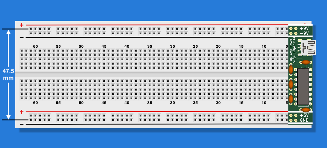
If you’re not familiar with a breadboard (see illustration above) there are typically “power rails” that run along the top and bottom of the breadboard. As illustrated above, the BB830 (and many other breadboards) often have power-rails in pairs. For my Op-Amp (Power Supply) Helper I designed it to supply +9V on the top row of holes (labeled with a red ‘+’ plus) and supply −9V on the horizontal row of holes just below it (labeled with the black ‘−’ minus).
The bottom pair of rails then carry the +5V from the USB supply (on the bottom row labeled with the red ‘+’ plus) and ground (on the last row labeled with the black ‘−’ minus). I marked these on the PCB itself so I can refer to it if I ever forget.
Using this then with an op-amp project then becomes simple. Plug the PCB into the breadboard and connect a USB cable between the PCB and a power source. Now you can easily tap the top pair of rails for the op-amp’s +9V and −9V needs and get other voltages you might need from the bottom rails.
I often make things I find useful in a quantity greater than I will need for myself, putting the extras up for sale for anyone else that might want them. In case you want one, I’ve put the Op-Amp Power Supply Helper up on Tindie.
Assembly instructions are here.